Maxitrak welcomes 2019


Firstly we would like to start this post by wishing all of our Maxitrak customers, old and new, a happy new year. With our 40th anniversary having just passed it is because of our fantastic customers that we can continue to do what it is that we love doing. What is it that we love doing? Well bringing you fantastic new locomotives of course!

We are kicking off 2019 with a big yellow (and maroon) bang in the shape of our EM Baldwin diesel locomotive. These engines were constructed by EM Baldwin and sons of Castle Hill, New South Wales, Australia.
The company supplied smaller locomotives for industry from the 1950s to the 1980s. Designs included shunting, mining and tunnel locomotives but the most common surviving engines were built for the Queensland sugar industry. At this time the extensive 2ft gauge lines were changing from steam to diesel traction. EM Baldwin built a large number of the replacement diesels to a continuously evolving design, to the extent that there are hardly two alike. Engines and gearboxes varied depending on power requirements and supplier’s delivery dates etc.
The usual sugar industry livery was bright yellow with red and white striped buffer beams, many enjoyed further enhancement with coloured stripes and panels giving the modeller many opportunities to customise the standard colour scheme.
Many of these engines are still hard at work in the cane cutting season and form the backbone of the largest surviving 2ft gauge industrial railway system in the world.

baldwin at leatherhead.

Our showroom locomotive 'Borcknel', (No the name doesn't mean anything, it was a plate we had spare and has now become a bit of an inside joke.) made it's debut at the SSME meet at Leatherhead just before Christmas. 

The big yellow monster definitely turned a few heads and quickly got to work pulling people around the track. With the ability to pull up to 8 adults on level track it has double the hauling capacity of our 5" Planet. 

maxitrak baldwin

When we were deciding on how we could improve our loco we decided a vinyl stripe in green and the Caterpillar badge would be an interesting choice, but as with the real-life engine, the customisation options are only limited by your imagination. We have also been working on the optional extra of the smoke machine. It certainly adds a bit of flourish. 

baldwin at leatherhead.

Thank you to everyone who has sent us their pictures and don't forget you too can share your photos by emailing them to Info@maxitrak.com with the subject line 'Share Station'

© Maxitrak Ltd
10-11 Larkstore Park,
Lodge Road,
Staplehurst,
Kent,
TN12 0QY
Email: Info@maxitrak.com

in training

Share Station - GL5 Appearances


It's hard to believe the sun is still out, what fantastic weather for getting out and running your maxitrak locos.

We recieved a lovely email from the satisfied owner of this lovely Class 25 who ran it at GL5 in Lincoln at the weekend. What an absoloutelyfantastic set up with all those wagons. It really goes to show that our locos have some pulling power. 

cllass 25

It's always great to see these trains out and doing what they were built to do, especially when they look as good doing it as this one does. The Class 25 is one of our popular 5" gauge electric engines and features a wealth of detail.

in training

Not only were we represented by the lovely Class 25 but there was also the apperance of one of our brand new Brush Shunters. This one has been kit built and finished to an amazingly detailed standard. I particularly like the plain yellow as oppesed to the standard wasp striping we usually see on this model.

Brush.

Thank you to everyone who has sent us their pictures and don't forget you too can share your photos by emailing them to Info@maxitrak.com with the subject line 'Share Station'

© Maxitrak Ltd
10-11 Larkstore Park,
Lodge Road,
Staplehurst,
Kent,
TN12 0QY
Email: Info@maxitrak.com

in training

Getting off Track


A Maxitrak Blog


The year 2008 was celebrated by extending the line at the top end across the lawn. As I intend to get to the top part of the garden the gradient had to be maintained across this section which was far from flat in the first place.
I started by marking the line of the track across the bottom of the lawn using a spade to put in two track bed edge lines following the desired curves. From here a section of grass was removed every ten feet or so. The earth was removed down to track bed level by eye, this was then followed up using the laser level. A peg was then driven in to the ground to mark rail level, and the track bed level adjusted to match. Each peg was given a rise of about two inches to get the correct gradient.
The rest of the grass was taken off and reused on embankment sides and the earth dug down to the track bed level guided by the pegs. As the next part of the construction needed embankments there was no problem using the excavated soil. The only hold up was that this part was through some very dense undergrowth that needed clearing before the soil could be tipped.


Crossing over
The resultant track bed was some distance below the grass level giving a cut soil edge in places nine or ten inches deep. I had some problems with soil erosion encroaching on the track in the rockery cutting and could for see problems here as well. The solution was to cut under the grass, fold the turf back, slope the soil down to track level and then replace the turf. This gave a nice grass slope down to rail level, it reminded me of the hidden wall used in stately homes to give an unobstructed view from the house but stopping the cattle from getting in to the garden and eating the flowers. I am told this is called a
“ha ha”, but my version only conceals the track and gives a safer edge to the cutting for children. The path the line had been following from the loop peters out near the pond so a fresh path was laid giving a short cut round the pond. The path crosses the line so as to give access to the lawn and hopefully to stop little ones walking through the rockery cutting.

Progress on this part was slow as dark evenings meant that work was restricted to weekends only. However we had track sufficient track down by early March to give us some running in the last of the winter snow flurries. The first anniversary of construction found the line starting on the embankment built from the lawn excavation. At this point we are quite near the bottom loop but have gained about two feet in height from this section. The exact height is difficult to judge due to the dense nature of the undergrowth but this all adds to the scenic appeal of the line when glimpses of different vistas appear and then disappear as you travel along.

Crossing over
The next section of track was though dense undergrowth, and needed a considerable amount of clearing. In addition the ground level fell away making all of this section on an embankment. Just to add to the interest there was a tree stump in the way, this had been a large poplar tree about twice the height of the house. The tree was in an unstable condition and was felled about four years ago but the stump was still very solid and only responded to being chipped away with an axe over an extended period of time. Fortunately the track only skirted the edge of this stump so the bulk of it remains firmly in place.

Some smaller trees and bushes were transplanted or simply uprooted, I like to transplant as much as possible though thanks to my gardening skills there is a good chance some will not survive.
The ground, once cleared, was covered in a layer of leaf litter. This is too soft to take the embankment so had to be cleared as well, however in keeping with the philosophy of reusing as much as possible I have found this a useful commodity for making paths and covering the edges of the track underlay. It is very light and washes away after a time but blends in well when it is there, and you get a fresh lot every year!

Crossing over

© Maxitrak Ltd
10-11 Larkstore Park,
Lodge Road,
Staplehurst,
Kent,
TN12 0QY
Email: Info@maxitrak.com

in training

Dead Mans Gulch


A Maxitrak Blog


I decided to use the same section of angle for the girder construction so as to keep the same look to the complete bridge. The ends of the girders are supported on two towers each consisting of four upright angles with diagonal bracing. These were stood on bricks standing on the sub soil in the same manner as the A frames. The two girders were then welded up with the top angle extended. This was then bolted to the top of the towers at each end, the ides is that each welded section is bolted to the next so the bridge can be disassembled if necessary and is also not too heavy to be put in place by one person.
The girders and towers are actually quite light and can easily be carried in to place.
The next section of track was welded up using extended heavy duty sleepers on the girder section, spanning across from girder to girder. This had to be aligned carefully as the track is curve over the bridge. The sleepers alone are not enough to hold the weight of the train so a diagonal brace was put in under every second sleeper transferring the weight to the bottom of the girders on each side. To prevent the girders spreading under the load a second lower brace was put in between each girder. This has given a strong light construction to the bridge section, there appears to be minimal deflection regardless of the weight put on the bridge.


Crossing over
 It was suggested I should invite a few stout friends for a ride to test the bridge for strength, in the event I used bags of ballast (more easily replaced than friends). The end of the bridge only required two more A frames to match up to the end of the existing embankment. The shorter of the two is the only part of the bridge to require any additional maintenance, as it was put in the embankment it did not reach the hard sub soil and has needed a bit of extra packing under the brick foundation.
The safety boards on each side of the track were extended over the bridge with a wider section on the girders where the track curve makes the bridge wider. It only remained to make a slight realignment to the track on the embankment and we were able to run the whole line in one go, about two hundred and fifty feet end to end.


Crossing over

Once complete the bridge was inspected by the family, “I’m not going on that! You know I get vertigo” was my wife’s comment. My daughter announced that Maddie was not going on it as it was too dangerous. My mum enquired what I was going to do with the hole, when I replied put rocks and ferns in it she suggested I leave out the rocks and put in some nice soft bushes to land in. As we have started to run trains attitudes softened, and everyone has now ridden the line including the bridge. All in all this section of the line has given the least trouble and required the least maintenance. Derailments are very rare on this section, christened “dead mans gulch” by the family, may be because everyone sits very upright and holds their breath on the high trestle.


© Maxitrak Ltd
10-11 Larkstore Park,
Lodge Road,
Staplehurst,
Kent,
TN12 0QY
Email: Info@maxitrak.com

in training

Share Station - Building from scratch


Well what a strange week it has been, from blazing sunshine and scorching tempratures over the bank holiday to fantastic lightning storms and downpours that caused flooding in the village we are based.  even with the poor weather we still got sent some fantastic images to share with you.

Galloping goose

We speak to all types of enthusiasts on a daily basis. From the well established engineer with vast knowledge and a skillset to match, to the amateur who has just begun to scratch the surface on this fantastic hobby. It can be daunting to start out, we at Maxitrak always try to keep it simple so that our models can be enjoyed by people of all ability levels. The owner of the locomotives in this weeks share station was once a school metal work teacher, and finds great enjoyment in building his locos from bits of office furniture and motors from the scooters discarded by grown up children. 

Playmobile train

He even took the time to transform a 'Playmobile' train to 5" gauge so that the younger generation could join in without the concern over more precious models. I personally love the idea of creating something to involve children, be they youngsters or grown up children, part of the joy of this hobby is the ability to share it with those around you. You knever know, you may just inspire the next generation of engineers! 

vexen.

This project is perhaps my favourite. Having the ability to form his own castings has really made this project his own. Each 5" cart requires a colossal 50 castings! The name Vexin was embossed to break up the panel and has a personal meaning to the owner as it is the name of the national park where they live. If you ever visit Paris and decide to climb the Eifel tower be sure to look out for this little railway as there is a chance you can see it from there.

I will leave this weeks Share Station with some words of wisdom from this talented engineer;
 "If you are trying to build, do not give up. It costs a fortune at first and absolutely everything needs a special tool and then it fouls up. To crown it all having thrown ten precious examples into the bin all you ever get from others at the best is a grunt of acknowledgement when you at last make a perfect one." It's not all smooth sailing and sometimes things go wrong, but every mistake is a learning experience. Learn from those around you, at clubs or online. You never know, they may be able to answer your question.

IThank you to everyone who has sent us their pictures and don't forget you too can share your photos by emailing them to Info@maxitrak.com with the subject line 'Share Station'

© Maxitrak Ltd
10-11 Larkstore Park,
Lodge Road,
Staplehurst,
Kent,
TN12 0QY
Email: Info@maxitrak.com

in training

Still Building Bridges


A Maxitrak Blog


I looked forward to the bridge construction with some trepidation, to finish the bottom loop I required a trestle bridge thirty feet long with a six foot single span section over the “big hole” This all had to be on 20ft radius just to add to the difficulty. I was originally going to make the bridge in wood like the traditional American trestle, but decided to stick to steel construction for ease of construction and maintenance. It then occurred to me that the length was actually quite short when you look at elevated track construction, many portable elevated tracks are much longer and are assembled, used and removed easily in a day.

Most steel elevated tracks use angle iron to give strength to a relatively long span between supporting legs. The rail usually forms an integral part of the structure adding to the strength rather than just sitting on the top. I was not able to use angle in any length on my bridge because of the curve required so instead I opted for the largest section steel flat that I could easily curve. I did think of having two or even three lighter rails to increase the strength and to give check rails in case of derailments but decided against this because of the difficulty of keeping the gauge and avoiding distortion when welding. In the end I opted for the rail in black mild steel flat 10mm by 20 mm, this size was about top whack for our set of bending rolls. As the rail was relatively light it did not allow a big span between supports, I put in an A frame every half meter run. As there were quite a lot of A frames they were made of relatively light construction using 25 by 25 by 3mm steel angle. The track was welded up in approximately two meter panels with sleepers made from 25 by 3mm steel flat every quarter meter. The sleepers did not need to be very stout as they either stood on an A frame or only served to hold gauge between the supports. The top of each A frame was extended to give a mounting point for timber side boards to support the train in the even of a derailment.


Crossing over


I commenced this part of the construction while pondering the design for the single span part over the big hole. To begin with there was a complete change of tooling, gone were the gentile battery drill, screwdrivers and BA size spanners. In came the big stick welder, angle grinder with cutting and grinding discs, mains power drill, large hammers etc.
I should at this stage say that I do not consider myself a great expert with the arc welder, I can usually stick two bits of metal together but the result may not look very pretty.

My first encounter with this form of welding was when working part time at a local boat yard. A Land Rover required a plate on the back of the chassis for the towing hook, I was persuaded to have a go. I was well used to gas welding having “practiced” on a number of old vehicles over the years but arc was new to me. I gave no guarantee as to the strength of the repair but fixed the plate in place. On my next visit I was gob smacked to see the same Land Rover pulling a very large boat out of the water on my welded tow hook, I simply could not watch and just had to go and do something else while this trial of strength was taking place. To my immense relief the hook staid in place!
I started by welding up the first track panel and set of A frames. I have learned with welded track to attach both rails to each sleeper at the same time, this reduces distortion as much as possible. Even so one panel got a bit of a twist in it. It is an indication of the strength of the panels when the only method that worked to remove the distortion was to lay the panel on the ground, drive the car over one end, place a large piece of timber through the other and then jump on it!

Crossing over

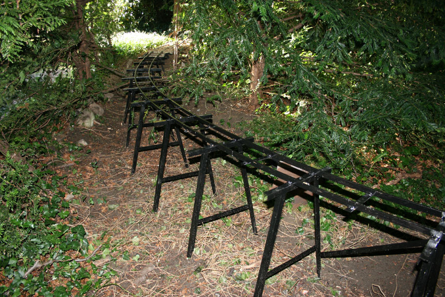
As the ground level fell away from the end of the embankment the A frames were made longer ranging from about half meter to one meter for the longest. All parts were given a coat of black Hammerite rust resistant paint and laid aside to dry.
Each A frame stood in a hole dug down to subsoil level, this hole then had a half brick laid in the bottom for the A frame to stand on. The holes were not easy to get to the correct level, I found a triangular paint scraper the best tool for cutting a flat base in the hard soil at the bottom of the hole. A small amount of soil was added or removed from the bottom of each hole until the brick and A frame stood at the correct level. The track panel was then placed on the A frames and a 6mm bolt used to bolt each A frame on to the sleepers. I expected to have to use several diagonal strips to strengthen the assembled bridge section, in the even only one was necessary. The finished section stood very firmly on its brick foundation but still allowed some final alignment before filling the earth back round the A frame legs. The second track panel was laid in the same manor with the track joint made by welding an angle to the end of each panel and bolting the two angles together below rail level with two M6 bolts. Once again only one diagonal brace was required, the whole assembly forming a very rigid structure joined to the existing rail formation with two cranked fishplates. This got the track to either side of the big hole, it only remained to make the girder bridge to complete the bottom loop.


Crossing over


© Maxitrak Ltd
10-11 Larkstore Park,
Lodge Road,
Staplehurst,
Kent,
TN12 0QY
Email: Info@maxitrak.com

in training

Home ← Older posts